Visio makes it easy for users to place shapes anywhere and provides connectors for maintaining connections between shapes. However, as diagrams get more complicated, users often look to Visio for help organizing shape placement and connector routing on the page. Unfortunately, while Visio's automatic layout functionality is quite powerful, many times the results are not good enough without tweaking the layout settings. In this post we'll look at one such scenario and try making a few changes to improve the final results.
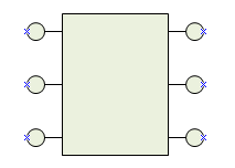
Here is a custom shape with several connection points on each side. Connectors are intended to glue to these points on the shape.
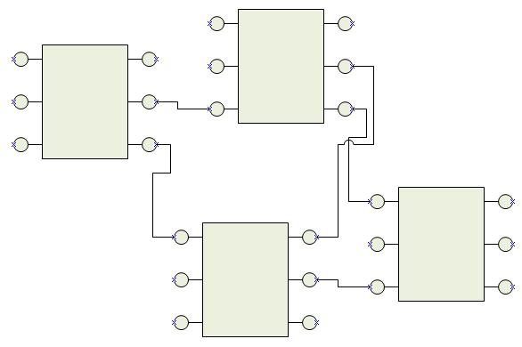
A diagram is created using this shape and connectors are added.
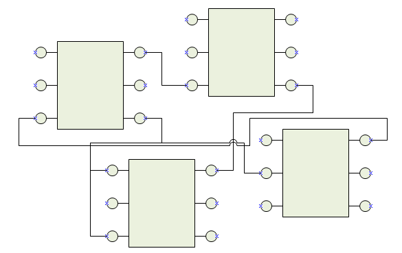
We now would like Visio to rearrange the shapes and reroute the connectors to create a cleaner, more readable diagram. Choosing Shape > Re-layout Shapes gives this result:

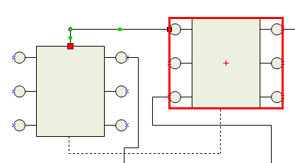
This result is not ideal. There are still overlapping connectors and too many bends. Visio is actually constrained by the way the connectors were glued to the shapes. The traditional way to glue connectors is to drag the end of the line to a connection point on the shape. This creates what is known as static glue in Visio. The connector remains associated with that connection point. Static glue has drawbacks for layout because it prevents Visio from routing to the nearest side of the shape. An alternative is using dynamic glue. To glue using dynamic glue, drag the end of the line to the center of the shape. A red outline rectangle will appear to indicate dynamic glue. The resulting red glue square has a slightly different look as well.
By switching all the connections over to dynamic glue, Visio can choose more efficient routes for the connectors. However, now Visio routes to locations on the shapes that we do not want. Our custom shape is not supposed to allow connections on the top or bottom.
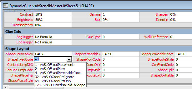
There is a Shapesheet cell that allows us to set some restrictions on dynamic glue so that Visio will not choose any arbitrary location to connect. The Shape Layout section has a cell named ShapeFixedCode that determines how connections can be made to a shape. By setting ShapeFixedCode to 64 on the custom shape we can force Visio to connect at connection points.
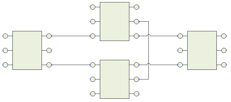
Now the automatic layout keeps the connectors glued to the connection points. Note that the glue style is still dynamic glue. Visio is free to choose which connection point is used for each connection. The result is better but still not ideal. There are still too many bends in the connectors as Visio must work in and around the shapes.
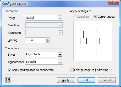
One final change can clean this layout up. Each drawing page has a default layout spacing, but the shapes you use in the drawing may not be suitable for that default. In this example, the default drawing spacing is 0.375 in. while the custom shape size is 1.25 in. x 1 in. That pushes the shapes too close together. By increasing the spacing between shapes, Visio can find better routes for the connectors. This is done in the Shape > Configure Layout dialog.
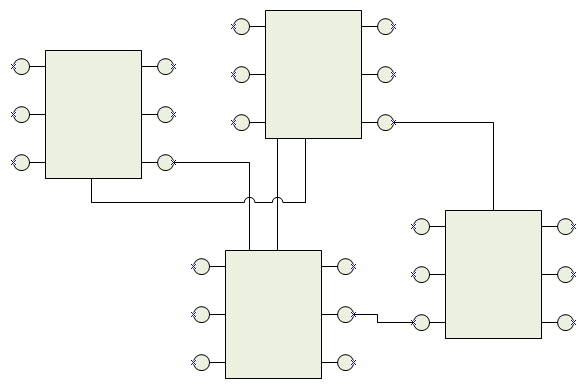
The end result is a much simpler arrangement with clean connector routes.
Dynamic glue adds flexibility to Visio's layout and routing optimizations and will result in a better looking diagram. The tradeoff is the inability to specify particular connection points for connectors. Visio assumes all connection points are equally valid. Hopefully the techniques presented in this post help you get better layout results. It is unfortunate that Visio's automatic layout needs this much tweaking to get good results, but it is challenging for a layout engine to produce optimal results across a huge variety of drawing types. As always, tell us your pain points, and we will try to address them in the future.