When creating and maintaining flowcharts, a pain point users suffer from is ensuring that the connectors between shapes look good. Visio introduced the dynamic connector many releases ago to help simplify diagram maintenance. Dynamic connectors in combination with dynamic glue allow Visio to choose the sides of shapes to glue your connectors for the best looking results.
In Visio 2010 we made improvements to Visio's routing engine to address some common flowcharting pain points. (For more on the dynamic connector and why you should use dynamic glue, see this previous post titled "Gluing It All Together". )
Improving Flowchart Readability
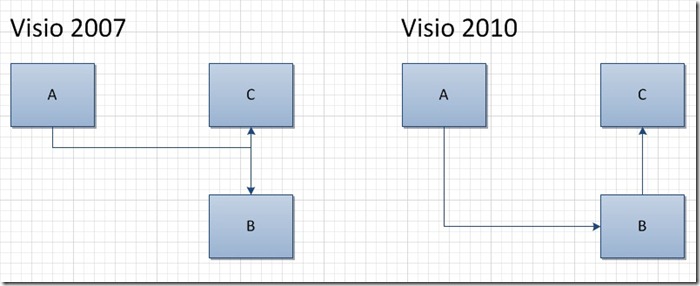
Clarity is important in flowcharts. Overlapping connectors flowing in opposite directions can create ambiguity about the meaning of the diagram. It is easy to get into a situation where two connectors appear visually to be connected, but were not explicitly connected by the diagram author. Visio 2010's routing engine detects such ambiguous situations and relocates connectors to actively avoid them.
Consider the example below where I draw two dynamic connectors: one from shape A to B and the other from B to C. In Visio 2007, this leads to an ambiguous drawing, where it appears as if shape A is connected to shape C. Visio 2010 moves the connector between A and B to an alternate side of shape B to resolve the ambiguity.
We made this design change based on user feedback. It scales to handle more than just a few connectors, and allows connectors to overlap when they are flowing in the same direction.
A consequence of this change is that if you open a diagram that was created in older versions of Visio in Visio 2010, as you edit your diagram, you may see connectors relocate to different sides of shapes. Note that Visio doesn't move glue points of connectors that are statically glued.
Relaxing Constraints on Flowchart Direction
Visio flowcharts that use the "Flowchart" routing style have a routing direction, like "Top to Bottom" or "Left to Right". In flowchart routing, this controls what sides of shapes dynamic connectors (mostly) connect to. Strict adherence to this direction can easily lead to situations where a dynamic connector takes a path around a shape with 5 segments.
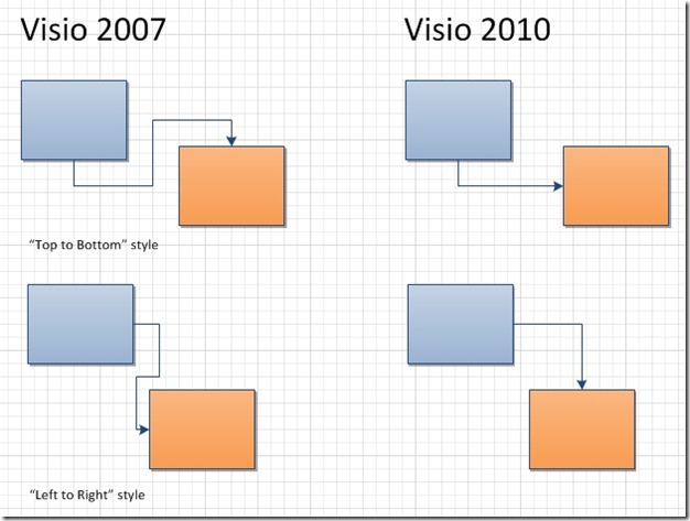
Using "Top to Bottom" as my routing direction, routes generally exit from the bottom of a shape and connect to the top of the shape, except in cases where shapes line up exactly.
In Visio 2010, we enable dynamic connectors to connect to alternate sides of shapes when the shapes are close to each other.
To strike a balance between having simple looking connectors and still adhering to the flowchart direction, Visio connects to non-standard sides of shapes when two shapes are close to each other in the axis of the routing direction.
As always, we're interested in your feedback on routing, so use the Send a Smile feedback tool or comment on this post to let us know what you think.


