In previous posts we introduced you to Containers and some of their special capabilities. We also introduced Lists through their use in Cross-functional Flowchart, Data Graphic Legends and Wireframe shapes. Finally we introduced Callouts as annotations on Visio diagrams. Containers, Lists and Callouts can be used in a wide variety of diagram types. This article explains how shape designers can go beyond the built-in shapes and create their own custom content.
Structured Diagrams
Collectively Containers, Lists and Callouts are referred to as Structured Diagram elements. They establish relationships with other shapes and those relationships define special behaviors. For example, shapes placed into a list are automatically arranged adjacent to one another; a callout shape moves whenever its target shape is moved. Structured Diagram elements are shapes themselves, and thus the special behaviors are defined through their ShapeSheet cells and values.
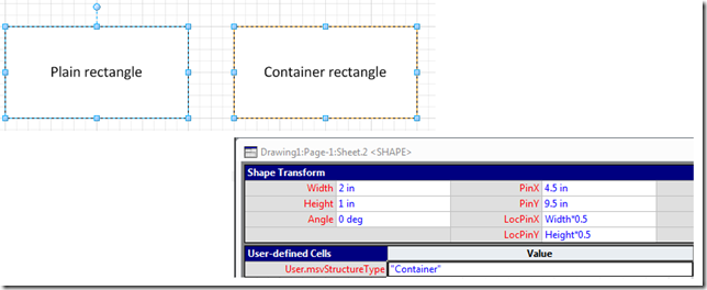
To designate any shape as a Container, List or Callout you only need to add one User-defined cell called User.msvStructureType. For the value enter “Container”, “List” or “Callout” as desired. This setting tells Visio that the shape is a Structured Diagram element and adds many of the Structured Diagrams behaviors to the shape. In the image below, a rectangle shape is transformed into a container shape by adding the User.msvStructureType cell and setting it to “Container”. However, there are additional settings available to customize the appearance and behavior of your shape, described in the rest of the article.
Container Shape Details
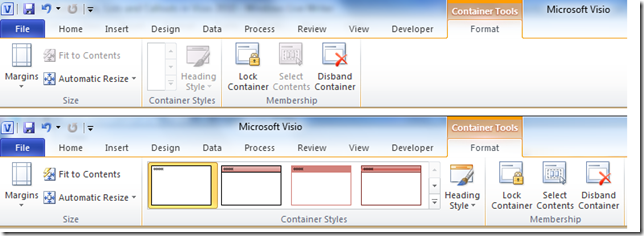
Any shape with User.msvStructureType = “Container” is treated by Visio as a Container. The following ShapeSheet cells define additional container properties, several of which can be configured in the Container Tools contextual tab in the Ribbon.
| Cell Name | Description |
| User.msvSDContainerMargin | Distance between container boundary and member shapes |
| User.msvSDContainerResize | Automatic resize behavior for shape (0 = No automatic resize; 1 = Expand as needed; 2 = Always fit to contents) |
| User.msvSDContainerStyle | 1-based index value for the current visual style of the container |
| User.msvSDContainerStyleCount | Total number of visual styles supported by the container |
| User.msvSDHeadingStyle | 1-based index value for the current visual style of the container heading |
| User.msvSDHeadingStyleCount | Total number of visual styles supported by the container heading |
| User.msvSDContainerLocked | Boolean value that prevents membership changes in the container |
| User.msvSDContainerRequiredCategories | Semi-colon delimited list of category names. Other shapes must have at least one matching name to be allowed as container members. |
| User.msvSDContainerExcludedCategories | Semi-colon delimited list of category names. Other shapes with at least one matching name are disallowed as container members. |
| User.msvSDContainerNoHighlight | Boolean value that suppresses the container highlighting when member shapes are selected or added to container |
| User.msvSDContainerNoRibbon | Boolean value that hides the Container Tools contextual tab in the Ribbon for this container |
| User.msvSDContainerHeadingEdge | String designating where the interior of the container is from the perspective of the container heading. Must be either “Left”, “Right”, “Top” or “Bottom”. |
| User.msvSDMembersOnHiddenLayer | Boolean value that determines whether Visio severs container relationships when the container or member is placed on a hidden layer. If True, Visio allows relationships to exist on the hidden layer. If False, Visio severs the relationships. |
Creating a visual style
If you are creating a container shape from scratch, you will notice that by default the container does not have any Container Style or Heading Style available in the Container Tools tab. Styles are a way to offer different looks for your container through some combination of geometry and formatting changes. The container shape can define multiple visual styles using the User.msvSDContainerStyle, User.msvSDContainerStyleCount, User.msvSDHeadingStyle and User.msvSDHeadingStyleCount cells (in short, the “Style” cells and the “Count” cells). Use the Count cells to tell Visio how many styles your shape supports for the overall container or for the heading. Then determine what ShapeSheet cells should be set for each style. Put formulas in each of these cells that depend on the value of the Style cells. Visio will check the style count and populate the ribbon galleries with each style defined by the container shape. When the user chooses a new style from the gallery, Visio puts that style index back into the Style cells to update the look of the container.
The container shapes in Visio 2010 vary in complexity. The containers in the Insert Container gallery have many visual styles and lots of formulas to change the appearance of the shapes. There are some simpler examples in the Wireframe shapes, which define just a few styles each.
Controlling container membership
Visio 2010 introduces the concept of Shape Categories to refine the membership behaviors of containers. This is the mechanism used by features such as Cross-functional Flowchart and Data Graphic Legends to ensure that only the right kinds of shapes participate in the list and container behaviors. A container shape can restrict membership by defining a required or excluded shape category. For this to work, a prospective member shape must have a User-defined cell User.msvShapeCategories in its ShapeSheet. The prospective shape lists one or more category names in a semi-colon delimited string. To only allow a specific category of member shape, a container can set that name in its User.msvSDContainerRequiredCategories cell. To allow most shapes as members but specifically exclude a category, a container can set that name in its User.msvSDContainerExcludedCategories cell. (Prospective shapes with no categories defined will not be allowed in a container with required categories, and they will always be allowed in a container with excluded categories.)
Creating a heading sub-shape
The heading of a container is simply the container shape’s text for basic containers. However, it is possible to achieve more sophisticated visual styles if the heading becomes its own shape. For this construction the container becomes a group and the heading is added as a sub-shape of the group. The primary benefit is that Visio can account for the heading sub-shape in sizing and layout operations to avoid putting member shapes on top of the heading. To designate a sub-shape as a heading for the container, add the cell User.msvStructureType to the sub-shape and give it the value “Heading”. Also you should properly set the User.msvSDContainerHeadingEdge cell in the sub-shape. These cells helps Visio understand how the heading is positioned relative to the interior of the container. For example, if the heading is near the left edge of the container then the correct value for the cell is “Right” (regardless of the heading’s angle). The interior of the container is on the right side of the heading.
Showing custom shapes in the Insert Container gallery
Visio provides several built-in container shapes in the Insert Container gallery located on the Insert tab of the ribbon. It is possible to override this set of shapes by creating a specially named stencil with other container shapes. Create a stencil named _CONTAIN.vss and place it in the user’s My Shapes folder.
List Shape Details
Any shape with User.msvStructureType = “List” is treated by Visio as a List. Note that Lists are also considered to be Containers. They simply have the additional capability of ordering and arranging their member shapes. All of the previously mentioned Container cells apply to list shapes. The following ShapeSheet cells define additional list properties.
| Cell Name | Description |
| User.msvSDListAlignment | Determines how member shapes are aligned in list (0 = Left; 1 = Center; 2 = Right for vertical lists. 0 = Top; 1 = Middle; 2 = Bottom for horizontal lists.) |
| User.msvSDListDirection | Direction that list arranges member shapes (0 = Left to Right; 1 = Right to Left; 2 = Top to Bottom; 3 = Bottom to Top) |
| User.msvSDListSpacing | Distance between list members |
| User.msvSDListItemMaster | Name or UniqueID of master shape to instance on Insert commands. Value must be placed inside a USE() function. |
| User.msvSDListNoReorder | Boolean value that prevents reordering of members. The list must also be locked via User.msvSDContainerLocked = True for setting to have any effect. |
| User.msvSDListRequiredCategories | Semi-colon delimited list of category names. Other shapes must have at least one matching name to be allowed as list members. |
| User.msvSDListExcludedCategories | Semi-colon delimited list of category names. Other shapes with at least one matching name are disallowed as list members. |
Specifying a shape to insert into lists
There are several ways to add a shape to a list: dragging and dropping the shape, clicking the blue insertion arrow that appears near the list edge or right-clicking an existing member and inserting a shape. Clicking the insertion arrow and right-clicking to insert both use the User.msvSDListItemMaster cell to determine what shape to add to the list. The name of the shape is placed in quotes inside a USE() function, such as USE(“Member shape”). It is also possible to automatically populate the list with some member shapes when the list is first dropped on the page. To do this put the following formula in the EventDrop cell of the list, repeating the DOCMD(2270) once for each member to be added:
IF(LISTMEMBERCOUNT()=0,DOCMD(2270)+DOCMD(2270)+DOCMD(2270),0)
Controlling list membership
Lists have their own cells to govern list membership. Use the User.msvSDListRequiredCategories and User.msvSDListExcludedCategories cells to restrict what shapes can become list members. Because lists are also containers, it is possible for shapes to become container members of the list. The standard User.msvSDContainerRequiredCategories and User.msvSDContainerExcludedCategories cells determine this behavior. By default Visio will attempt to add a shape to a list as a list member, but if that fails it may try to add it as a container member. You should manage both sets of cells to ensure the right results.
Callout Shape Details
Any shape with User.msvStructureType = “Callout” is treated by Visio as a Callout. Callout shapes must also have a control handle with the Controls row named Controls.Association. Visio manages the relationship with the callout’s target shape through this row in the ShapeSheet. The following ShapeSheet cells define additional callout properties.
| Cell Name | Description |
| User.msvSDCalloutNoHighlight | Boolean value that suppresses the highlighting on the callout target shape |
| User.msvSDTargetIntersection | Location in page coordinates of the intersection between the geometric boundary of the target shape and a virtual line drawn from the center of the callout to the center of the target shape. This is a read-only cell set by Visio. |
Showing custom callout shapes in the Insert Callout gallery
Visio provides several built-in callout shapes in the Insert Callout gallery located on the Insert tab of the ribbon. It is possible to override this set of shapes by creating a specially named stencil with other callout shapes. Create a stencil named _CALLOUT.vss and place it in the user’s My Shapes folder.
Summary
This post gives shape designers the detailed information needed to create their own Containers, Lists and Callouts. Please tell us what you think by using the Send a Smile feedback tool or by commenting on this post.


